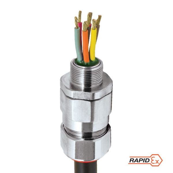
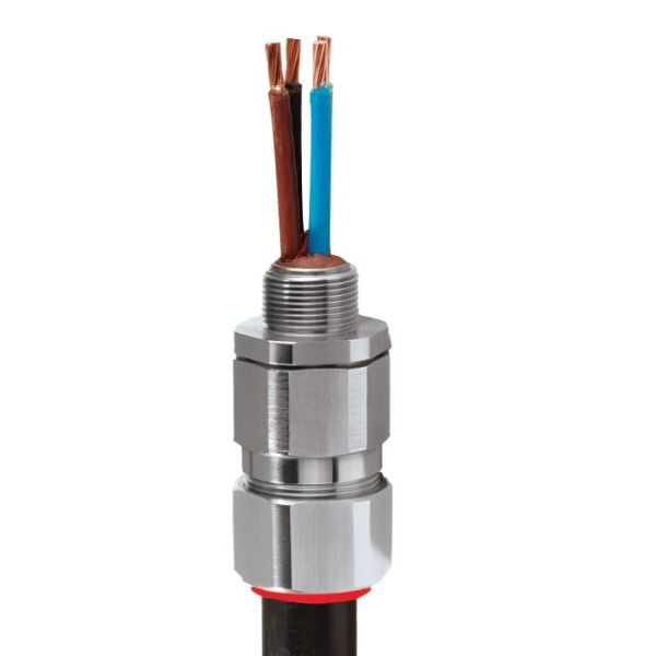
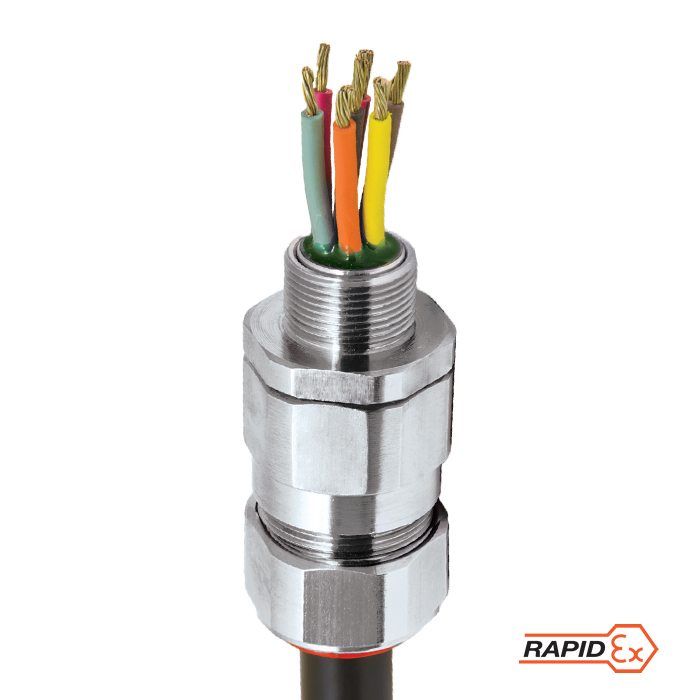
Product Features
Table Data
Downloads
Recommended Products
-
CategoriesCable Glands
-
Design SpecificationBS 6121:Part 1:1989, IEC 62444, EN 62444
-
Mechanical Classification*Impact = Level 8, Cable Anchorage = Type D
-
Ingress Protection Rating **IP66, IP67 and IP68***
-
Cable TypeLead Sheathed & Single Wire Armour (LC/SWA), Lead Sheathed & Aluminium Wire Armour (LC/AWA), Lead Sheathed & Wire Braid Armour (LC/SWB), Lead Sheathed & Pliable Wire Armour (LC/PWA), Lead Sheathed & Steel Tape Armour (LC/STA), Lead Sheathed & Aluminium Strip Armour (LC/ASA)
-
MaterialBrass, Electroless Nickel Plated Brass, Stainless Steel, Aluminium
-
Seal MaterialCMP SOLO LSF Halogen Free Thermoset Elastomer / RapidEx Barrier Compound
-
Armour ClampingDetachable Compound Tube / Cone and AnyWay Universal Clamping Ring
-
Sealing Area(s)Inner Compound Barrier and Outer Sheath
|
Cable Gland Size |
Available Entry Threads 'C' |
Number of Cores |
Diameter Over Conductors 'A' |
Lead Sheath Diameter 'G' |
Overall Cable Diameter 'B' |
Armour Range | Across Flats 'D' |
Across Corners 'D' |
Protrusion Length 'F' |
Shroud |
Cable Gland Weight (Kgs) |
|||||||||
| Standard | Option | Grooved Cone (X) |
Stepped Cone (W) | |||||||||||||||||
| Metric |
Thread Length (Metric) 'E' |
NPT |
Thread Length (NPT) 'E' |
NPT | Min | Max | Min | Max | Min | Max | Min | Max | Max | Max | ||||||
| 20S16 | M20 | 15.0 | ½' | 19.9 | ¾" | 21 | 7.8 | 3.1 | 7.8 | 6.1 | 13.1 | 0.3 | 1.0 | 0.8 | 1.25 | 30.5 | 33.6 | 62.0 | PVC06 | 0.25 |
| 20S | M20 | 15.0 | ½' | 19.9 | ¾" | 21 | 11.0 | 6.1 | 11.0 | 9.5 | 15.9 | 0.3 | 1.0 | 0.8 | 1.25 | 30.5 | 33.6 | 62.0 | PVC06 | 0.23 |
| 20 | M20 | 15.0 | ½' | 19.9 | ¾" | 21 | 12.6 | 6.5 | 13.4 | 12.5 | 20.9 | 0.4 | 1.0 | 0.8 | 1.25 | 30.5 | 33.6 | 63.0 | PVC06 | 0.24 |
| 25S | M25 | 15.0 | ¾' | 20.2 | 1" | 30 | 17.5 | 11.1 | 19.3 | 14.0 | 22.0 | 0.4 | 1.2 | 1.25 | 1.6 | 37.5 | 41.3 | 69.5 | PVC09 | 0.37 |
| 25 | M25 | 15.0 | ¾' | 20.2 | 1" | 30 | 17.5 | 11.1 | 19.3 | 18.2 | 26.2 | 0.4 | 1.2 | 1.25 | 1.6 | 37.5 | 41.3 | 69.5 | PVC09 | 0.37 |
| 32 | M32 | 15.0 | 1' | 25.0 | 1 ¼" | 50 | 23.6 | 17.0 | 25.5 | 23.7 | 33.9 | 0.4 | 1.2 | 1.6 | 2.0 | 46.0 | 50.6 | 75.0 | PVC11 | 0.57 |
| 40 | M40 | 15.0 | 1 ¼' | 25.6 | 1 ½" | 59 | 27.9 | 22.0 | 31.2 | 27.9 | 40.4 | 0.4 | 1.6 | 1.6 | 2.0 | 55.0 | 60.5 | 75.0 | PVC15 | 0.80 |
| 50S | M50 | 15.0 | 1 ½' | 26.1 | 2" | 89 | 35.2 | 29.5 | 37.2 | 35.2 | 46.7 | 0.4 | 1.6 | 2.0 | 2.5 | 60.0 | 66.0 | 77.0 | PVC18 | 0.90 |
| 50 | M50 | 15.0 | 2' | 26.9 | 2 ½" | 115 | 40.4 | 35.6 | 42.6 | 40.4 | 53.0 | 0.6 | 1.6 | 2.0 | 2.5 | 70.0 | 77.0 | 77.0 | PVC21 | 1.19 |
| 63S | M63 | 15.0 | 2' | 26.9 | 2 ½" | 115 | 45.6 | 40.1 | 48.5 | 45.6 | 59.4 | 0.6 | 1.6 | 2.0 | 2.5 | 75.0 | 82.5 | 79.7 | PVC23 | 1.41 |
| 63 | M63 | 15.0 | 2 ½' | 39.9 | 3" | 115 | 53.7 | 47.2 | 54.2 | 54.6 | 65.8 | 0.6 | 1.6 | 2.0 | 2.5 | 80.0 | 88.0 | 80.3 | PVC25 | 1.44 |
| 75S | M75 | 15.0 | 2 ½' | 39.9 | 3" | 140 | 59.0 | 52.8 | 60.2 | 59.0 | 72.0 | 0.6 | 1.6 | 2.0 | 2.5 | 90.0 | 99.0 | 86.8 | PVC28 | 2.13 |
| 75 | M75 | 15.0 | 3' | 41.5 | 3 ½" | 140 | 64.2 | 59.1 | 65.2 | 66.7 | 78.4 | 0.6 | 1.6 | 2.5 | 3.0 | 100.0 | 110.0 | 88.3 | PVC30 | 2.57 |
| 90 | M90 | 20.0 | 3 ½' | 42.8 | 4" | 140 | 75.3 | 66.6 | 77.1 | 76.2 | 90.3 | 0.8 | 1.6 | 3.15 | 4.0 | 115.0 | 126.5 | 102.1 | PVC32 | 3.75 |
| 100 | M100 | 20.0 | 3 ½' | 42.8 | 4" | 200 | 85.6 | 76.0 | 88.1 | 86.1 | 101.4 | 0.8 | 1.6 | 3.15 | 4.0 | 127.0 | 139.7 | 114.0 | LSF33 | 4.87 |
| Dimensions in millimeters unless otherwise stated | ||||||||||||||||||||
Data Sheets

CMP PX2KWREX | Explosive Atmosphere Barrier Cable Gland
• RapidEx liquid pour sealing system, Enhances reliability, reduces risk ...

CMP PX2KREX | Explosive Atmosphere Barrier Cable Gland
• RapidEx liquid pour sealing system, Enhances reliability, reduces risk, Reduces...

CMP PX2K | Explosive Atmosphere Cable Gland
• Metal-to-metal armour clamping
• Direct & remote installation, compound...

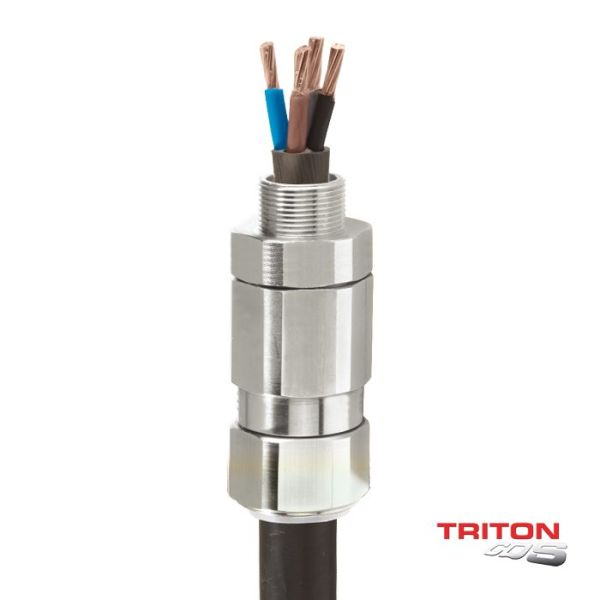
CMP Triton CDS | Explosive Atmosphere Cable Gland
• Fully sequential, three step installation procedure, reduces installation times, cost...
